This is a 15W audio amplifier using 3 transistors.

The gain of the circuit is approximately 40DB (X90, Vcc=12V)
The distortion 0.1-10%.
Use 4Ω or 8Ω.

Thanks.

This circuit is an electronic bell, it produce a tone like a real bird, useful as a doorbell, alarm, or between two rooms, floors like i did.

_ P1 is of experimental value. Start with 220 Ohms or so and modify to suit your needs, you can also change C3,C4,C5 to get more different tones, The transistor is a general purpose kind and is not critical, almost any
small PNP type will work.
small PNP type will work.
_ L1 is a bell-transformer which is usually already present in the house, if you wish, you can use a battery instead of the bell transformer, Just hookup a 9-volt battery (or wall adapter) to The +/- .
_ Diode (D1) is required as a rectifier for use with the bell transformer and to protect the circuit from accidental polarity reversal.
_ Diode (D1) is required as a rectifier for use with the bell transformer and to protect the circuit from accidental polarity reversal.
_ L2 can be found in an old transistor radio, they look like miniature transformers and are usually colored red or green, you have to try with different transformers as the sound can vary depending on the winding.
_ The speaker is a 8 Ohm type and must be larger than 200milli-Watt. I used a 2Watt type, but anything over 0.2W will do.
_ The speaker is a 8 Ohm type and must be larger than 200milli-Watt. I used a 2Watt type, but anything over 0.2W will do.
This video shows the circuit working, by changing certain values you get mores sounds...
It really sounds like a bird and when you release the doorbell button the sound slowly fades away. I have used this circuit in my house, and even build the circuit for others.


Remember to have fun!!!
Thanks
This circuit consists of negative resistance in transistors.


A number of demonstratons of this circuit have appeared on YouTube.
Thanks

A common NPN
transistor is used. In the circuit, a 1k resistor charged the 470u
uf capacitor until the voltage became large enough to get the
emitter-base junction to avalanche. At this point transistor turned on quickly and partially
discharged the 470 uf capacitor through the LED and the 100 Ohm current
limiting resistor. The current wavform, which is the voltage drop
across the 100 Ohm resistor, Peak current was 26 milliamps, and the transistor continued to
discharge the capacitor until conduction suddenly ceased at 6
milliamps. After the transistor stopped conducting, the
capacitor began
charging again, thus starting a new cycle.By changing C1 frequency change.

A number of demonstratons of this circuit have appeared on YouTube.
Thanks
This circuit is a simple flasher it can be used with car bulbs or just leds.
It consists of two tansistors, the flashing rate can be changed by changing C1 value.
It can flash globes, LEDs and pulse all types of devices such as motors, and piezo diaphragms...

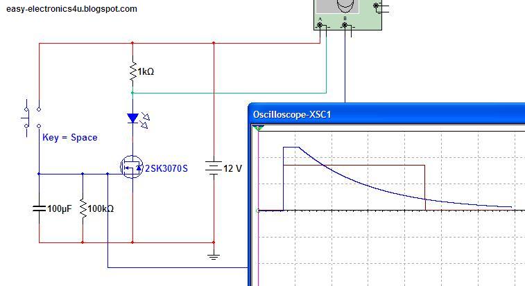
This two circuits used to switch ON Or Off any DC load after delay:
First: Off after delay.

- When S1 pressed, the capacitor is charged to Vcc and the mosfet saturate and the bell will loud (you can change the buzzer with any load you want).
- After S1 is released the capacitor start discharging through R1, when the capacitor voltage reach certain value the mosfet blocks the current and the load switched off.
_ The blocking voltage change from transistor to another, for exemple 2Sk3070 when the gate voltage reach 2.1V it blocks the current. so the function time is when the voltage decrease from vcc(12V) to 2.1.
_ To calculate the time you can use this formula ( V = V0 * e^(-t/RC) ) or the Capacitor Discharge Calculator script tool HERE:
- V (Threshold Voltage: the capacitor discharge value, for 2SK3070 2.1V)
- V0 (Initial Charge Voltage: Vcc in our exemple 12V)
- R (the discharge resistance Value (Ω) in the exemple 100KΩ)
- C (Capacitor Value (F) in the exemple 100uF)
- t (time of discharging that we want to calculate (s) )
- we want (t): e^(-t/RC) = V/V0
- -t/RC = Ln(V/V0)
- t = -Ln(V/V0) * R * C
- t = -Ln (2.1/12)*100000*0.0001
- t = 17.42 s
- So for R=100KΩ C=100uF the delay is 17second
Use the same equation to calculate the resistor or the capacitor value.
 Second: On after delay.

The only difference is the transistor.
Thanks

The only difference is the transistor.
- When S2 is closed the load switched On immediately (capacitor discharged).
- When S1 is pressed (S2 closed), the capacitor is charged to Vcc and the mosfet saturate and Vds≈0, that means the transistor base Vbe≈0 which means the load is Off.
- After S1 is released the capacitor start discharging through R1, when the capacitor voltage reach certain value the mosfet blocks the current Vds≈Vcc, the transistor saturate and the load switched On.
Thanks
We will now see how we can switch AC loads using Mosfet's transiostors (using mosfet's as relay)
Two MOSFETs with their source pins connected together will drive AC loads.


An Opto-isolator or logic gates can be used to switch the mosfets on and off, to prevent damaging mosfet's because we want the mosfets to be full on (saturation region) or full off , if you apply an insuffisant voltage to the gate of the mosfet's it will function in the linear region and the power dissipation will be splited between the load and the mosfet, which will burn the mosfet at high currents.

Thanks.
This simple circuit generates stable square
wave at differents frequencies, using from 3v to 12v cells as power supply.
An useful feature of this circuit is that the frequency can be changed by changing a capacitor value, a switch can be add to choose between various frequencies.


Thanks
An useful feature of this circuit is that the frequency can be changed by changing a capacitor value, a switch can be add to choose between various frequencies.


Thanks


