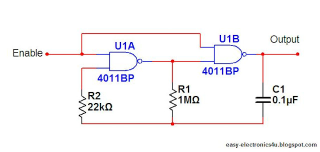
This circuit is a rectangular oscillator, that generates a square wave form, the circuit uses NAND logic gates, using CD4011 (contain 4 nand gates), the generated signal can be used as an audio alarm (by connecting a speaker directly to the output), or amplified and used as an inverter...
 The enable input should be (+V) so that the circuit oscillates, if it's low, the output will remain at High (+V), If you do not need a controlled input, you can connect the two inputs of the two gates together and remove the connection between the first and the second gate. (like the picture)
This may simplify the wiring.
Caution: the common point of the resistors and the capacitor is not grounded.
Thanks


5 comments:
This is certainly one of the most valuable posts. Great tips from beginning till end. Lots of suggestions for me and for people. Superb work
Neon Lights
Very interesting and helpfull. Dident know this was possible. is there perhaphs a way to modulate frequency by chaning resistor values ?
I am happy to find much useful information in the post, writing sequence is awesome, I always look for quality content, thanks for sharing.
UV Disinfection Lamp
Excellent article! We are linking to this great article on our website. Keep up the good writing.Hacking BlogsHack Instagram Psychology Hack
I tried to simulate this circuit. but could not get the output in multisim14
Post a Comment