Showing posts with label Switches. Show all posts
Showing posts with label Switches. Show all posts
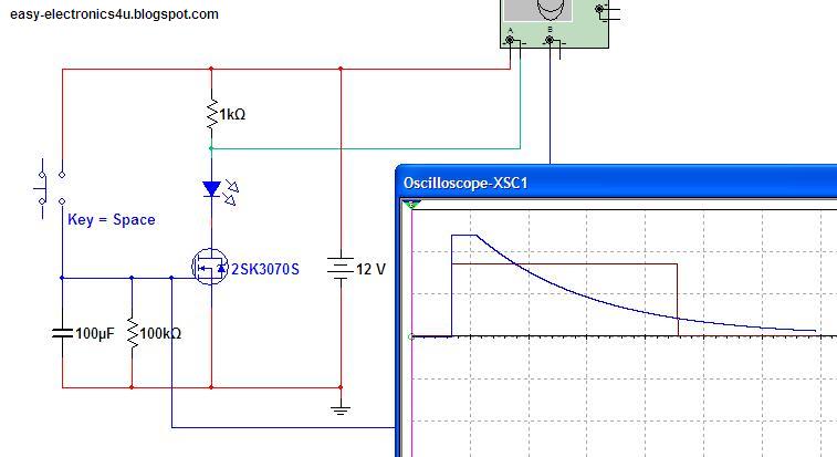
This two circuits used to switch ON Or Off any DC load after delay:
First: Off after delay.

- When S1 pressed, the capacitor is charged to Vcc and the mosfet saturate and the bell will loud (you can change the buzzer with any load you want).
- After S1 is released the capacitor start discharging through R1, when the capacitor voltage reach certain value the mosfet blocks the current and the load switched off.
_ The blocking voltage change from transistor to another, for exemple 2Sk3070 when the gate voltage reach 2.1V it blocks the current. so the function time is when the voltage decrease from vcc(12V) to 2.1.
_ To calculate the time you can use this formula ( V = V0 * e^(-t/RC) ) or the Capacitor Discharge Calculator script tool HERE:
- V (Threshold Voltage: the capacitor discharge value, for 2SK3070 2.1V)
- V0 (Initial Charge Voltage: Vcc in our exemple 12V)
- R (the discharge resistance Value (Ω) in the exemple 100KΩ)
- C (Capacitor Value (F) in the exemple 100uF)
- t (time of discharging that we want to calculate (s) )
- we want (t): e^(-t/RC) = V/V0
- -t/RC = Ln(V/V0)
- t = -Ln(V/V0) * R * C
- t = -Ln (2.1/12)*100000*0.0001
- t = 17.42 s
- So for R=100KΩ C=100uF the delay is 17second
Use the same equation to calculate the resistor or the capacitor value.
 Second: On after delay.

The only difference is the transistor.
Thanks

The only difference is the transistor.
- When S2 is closed the load switched On immediately (capacitor discharged).
- When S1 is pressed (S2 closed), the capacitor is charged to Vcc and the mosfet saturate and Vds≈0, that means the transistor base Vbe≈0 which means the load is Off.
- After S1 is released the capacitor start discharging through R1, when the capacitor voltage reach certain value the mosfet blocks the current Vds≈Vcc, the transistor saturate and the load switched On.
Thanks

We will now see how we can switch AC loads using Mosfet's transiostors (using mosfet's as relay)
Two MOSFETs with their source pins connected together will drive AC loads.


An Opto-isolator or logic gates can be used to switch the mosfets on and off, to prevent damaging mosfet's because we want the mosfets to be full on (saturation region) or full off , if you apply an insuffisant voltage to the gate of the mosfet's it will function in the linear region and the power dissipation will be splited between the load and the mosfet, which will burn the mosfet at high currents.

Thanks.


